* On your first PCB Assembly order!
* Up to $300 discount
 C - A L L E Y
 Home | Events | PCB | About Us | News | Contact Us
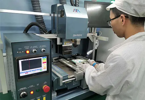
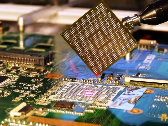
In the PCBA manufacturing industry, Ball Grid Array (BGA) packages are widely used in CPUs, GPUs, southbridge chips, and power management modules due to their high density and high performance. However, BGA rework (removal, ball placement, and reattachment) requires localized high-temperature heating, with peak temperatures typically reaching 240–260°C. Adjacent plastic-packaged components (such as connectors, electrolytic capacitors, QFNs, molded inductors) and the PCB substrate itself are sensitive to thermal shock. Poor thermal distribution control can lead to component cracking, solder joint remelting and displacement, package cracks, PCB delamination (blow-out), or pad peeling. Statistics indicate that approximately 60% of BGA rework failures are not caused by the chip body itself but by damage in the heat-affected zone (HAZ).
1. Typical Damage Modes Caused by Uncontrolled Thermal Distribution
1.1 Secondary Solder Remelting on Adjacent Components
When passive components such as 0402, 0603 resistors/capacitors or small-pitch QFNs are located within 5mm of the BGA edge, excessive lateral heat diffusion during rework can raise the solder terminal temperature above the liquidus (approximately 217°C), causing component shifting, tombstoning, or bridging.
1.2 Moisture Vaporization and Package Cracking in Molded Components
Non-dried plastic-packaged devices (e.g., aluminum electrolytic capacitors, MOSFETs) contain internal moisture that rapidly vaporizes at high temperatures. If the ramp rate exceeds 3°C/s, internal steam pressure can cause top-surface rupture or side-layer delamination.
1.3 PCB Resin and Copper Foil Delamination
Prolonged local temperatures above the glass transition temperature (Tg, typically 130–170°C) reduce resin adhesion. Combined with Z-axis coefficient of thermal expansion (CTE) mismatch, this produces ring-shaped white spots or pad lifting around the BGA pad area.
2. Core Hardware and Process Parameters for Thermal Distribution Control
2.1 Heating Source Selection for Rework Equipment
Infrared (IR) bottom preheating + top hot air: Bottom IR provides uniform background heat (80–150°C), reducing overall PCB temperature differentials; top hot air focuses on the BGA center. Prioritize closed-loop temperature-controlled hot-air nozzles, with an inner diameter 2–4mm larger than the BGA edge size, to prevent hot air from directly impinging on surrounding components.
Laser-assisted heating: Suitable for very small BGAs, but the laser spot requires galvanometer scanning; otherwise, the single-point energy is too concentrated. Not recommended for multi-row solder-ball devices.
2.2 Critical Temperature Profile Settings (for Lead-Free Sn96.5Ag3.0Cu0.5)
Preheat stage: From room temperature to 150°C, ramp rate 1.0–1.5°C/s, with bottom preheating enabled to bring the entire board to 100–110°C.
Soak stage: 150–190°C, duration 60–90s, activating flux and achieving thermal equilibrium across the board. During this stage, thermocouple measurements at 5mm from the BGA edge must remain below 160°C.
Reflow stage: Peak temperature 245–250°C (at the BGA center solder balls), duration 10–15s. Top hot-air flow rate controlled at 15–20L/min to avoid strong convection pushing heat outward. Cooling stage: Natural or forced air cooling (not directly blowing onto the BGA), cooling rate ≤4°C/s, until board surface temperature drops below 80°C before handling.
2.3 Thermal Isolation and Shielding Techniques
Metal stencil mask (protection cover): Before BGA rework, place a stainless steel or aluminum cutout shield over adjacent sensitive components, with a thickness of 0.2–0.5mm and an opening exposing only the BGA area. This cover reflects part of the IR radiation and absorbs kinetic energy from the hot air.
High-temperature tape (polyimide) with aluminum foil overlay: For components with height ≤2mm, first apply a layer of Kapton tape, then cover with aluminum foil tape (aluminum side outward) to reflect heat. Field measurements show this reduces surface temperature by 30–50°C.
Thermal conductive filler blocks (silicone pads): For nearby large connectors, use thermally conductive silicone pads connected to an external heat sink via a clamping fixture before rework. However, ensure clamping pressure ≤0.5MPa to avoid crushing solder joints.
3. Real-Time Monitoring and Dynamic Compensation Strategies
3.1 Multi-Point Thermocouple Placement
Deploy at least four K-type thermocouples: under the BGA center (via embedded holes), at the BGA edge, on the surface of components 5mm from the BGA, and on the PCB backside center. Use the rework station's multi-channel recorder to monitor real-time differentials. If surrounding component temperatures exceed 180°C, manually reduce the hot-air temperature or increase bottom preheating compensation (reducing the share of top heating).
3.2 Thermal Imaging-Assisted Adjustment
Mount an infrared thermal imaging probe (non-contact) on the side of the rework head, scanning the thermal field distribution every 2 seconds. If a hot spot shift is detected, immediately adjust the nozzle XY position or tilt angle (±3°). A common criterion: the temperature difference between the BGA center and the 4mm periphery should be within 40°C; if the differential is too large, increase the bottom preheat temperature by 5–10°C.
3.3 Segmented Heating and Intermittent Pulsing
For high-thermal-mass boards with PCB thickness >2.0mm or copper layers >6, adopt a "heat 5s – pause 2s" pulse mode. This allows heat to diffuse laterally through the copper foil, preventing instantaneous surface overheating. This pulse mode can reduce peak temperatures of surrounding components by approximately 15°C.
4. Mandatory Verification Tests Before Batch Rework
Prior to formal batch rework, the following three verifications must be performed. Otherwise, production line entry is prohibited:
Thermocouple attachment soldering test: Solder a test BGA (non-functional) using the defined profile, and record the peak surface temperatures of designated vulnerable surrounding components (e.g., MLCCs). The maximum must remain below the storage temperature tolerance stated in their datasheets (typically 125°C or 150°C).
Red dye or dye-and-pry penetration test: After rework, remove the BGA and apply red dye penetration to surrounding components and the PCB substrate. If cracks or delamination are observed, extend the soak-stage duration by 20s to reduce thermal stress.
Electrical functional test and X-ray inspection: All reworked boards must pass 100% in-circuit test (ICT) and X-ray solder void inspection (void ratio <25%), while also checking for solder balls or bridging on adjacent component terminals.
Conclusion
Thermal distribution control in BGA rework is essentially about converting a "point heat source" into a "surface thermal field." Bottom preheating carries the bulk thermal load, while top hot air provides only the localized melting energy necessary for the BGA. Combined with physical shielding and real-time feedback, this approach strictly limits the temperature rise of surrounding components below their tolerance thresholds. Independent website operators can provide customers with rework process document templates, thermal isolation consumables lists, and thermal imaging monitoring reports based on these parameters. These substantive technical materials build long-term collaboration more effectively than price competition. Recording the thermal profile and surrounding component types after each rework session to build an in-house database is the critical path to improving rework yield from 90% to above 98%.

Please send Email to kspcba@c-alley.com or call us through +86 13828766801 Or submit your inquiry by online form. Please fill out below form and attach your manufacturing files( PCB Gerber files and BOM List) if need quotation. We will contact you shortly.
 +86 13828766801
 kspcba@c-alley.com
 https://www.kingshengpcba.com/
 2/F, Building 6, Tangtou 3rd Industrial Zone, Tangtou Community, Shiyan Town, Baoan District, Shenzhen, China, 518108
We would also like to thank our customers for their trust and support. The company's outstanding achievements are mainly due to the loyalty of our customers, which also encourages and spurs our company to forge ahead.


