* On your first PCB Assembly order!
* Up to $300 discount
 C - A L L E Y
 Home | Events | PCB | About Us | News | Contact Us
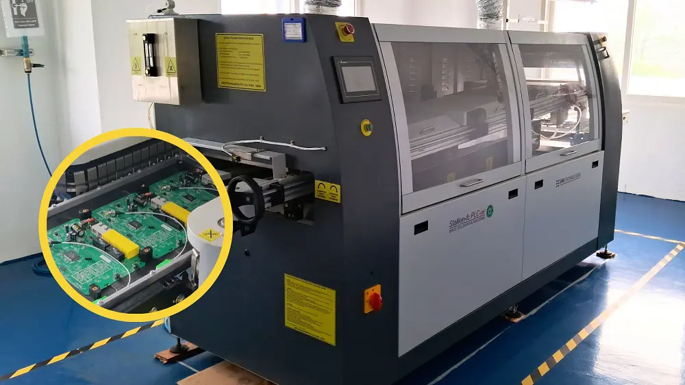
In PCBA mass production, wave soldering remains a highly efficient process for through-hole and mixed-technology boards. However, as electronics become smaller and more densely populated, solder bridging (or "solder short") has become one of the most common and costly defects. For PCBA manufacturers, systematically solving bridging issues is not only a technical necessity but also a powerful way to demonstrate process capability and win customer trust.
This article provides a concise, field-proven approach to eliminate wave soldering bridges—covering root causes, a three-step closed-loop solution, and a real improvement case.

Ⅰ. Root Cause Analysis: Why Does Bridging Occur?
Bridging typically happens when excess solder fails to separate between adjacent pins (e.g., ICs, connectors, pin headers). Based on real production experience, the main causes fall into five categories:
1.1 PCB design: Insufficient pad spacing (<0.8mm is risky), lack of solder mask dams or solder thief pads, component orientation parallel to solder flow.
1.2 Flux: Low activity, uneven spray coverage, excessive drying during preheat, or high solid content increasing surface tension.
1.3 Process parameters: Solder pot temperature too high or low (optimal 250–265°C for lead-free), conveyor angle <5°, excessive wave height, or chain speed >1.5 m/min.
1.4 Components & tooling: Long lead protrusion (>1.5mm), poor coplanarity, or pallet shadow effect causing uneven heat distribution.
1.5 Environment & maintenance: High copper or gold contamination in solder (>0.3% Cu), unstable wave shape, nozzle blockage, or high workshop humidity affecting flux performance.
Ⅱ. Systematic Solution: The Three-Step Closed-Loop Method
Step 1 – Design Optimization (Prevention First)
Ensure clear solder mask dams between adjacent pads (minimum 0.1mm width).
Add solder thief pads or "dummy pads" at the end of dense pin rows to drain excess solder.
Orient components perpendicular to solder flow direction to improve solder separation.
Provide DFM (Design for Manufacturing) review services to customers early in the product lifecycle.
Step 2 – Fine-Tune Process Parameters
Flux selection: Use a high-activity, low-solid-content (≤5%) flux suitable for lead-free or leaded alloys. Verify even spray coverage using thermal paper or glass plate test.
Preheat optimization: Set preheat so that top-side board temperature reaches 90–110°C (lead-free). This activates flux without burning it or causing dry-out.
Solder pot temperature: Maintain at the middle of the recommended range, typically 260°C for lead-free SAC305 alloy.
Conveyor angle & speed: Set angle to 5–7° (optimally 6°) and chain speed to 1.0–1.2 m/min. Lower speeds give more time for solder drainage.
Wave height: Adjust to just touch the bottom of the board (typically 0.5–0.8 of the wave height relative to nozzle). Avoid excessive pressure.
Dual-wave mode: For difficult dense pins, use turbulent wave (for wetting) followed by laminar wave (for separation).
Step 3 – Maintenance, Tooling & Monitoring
Nozzle cleaning: Clean wave solder nozzles daily or weekly to ensure a flat, stable wave.
Solder bath management: Analyze solder composition weekly. If copper exceeds 0.3%, dilute with pure tin or replace the bath.
Pallet improvement: Add flow deflectors or slots near dense pins to eliminate shadow effects and improve solder drainage.
Operator training: Train staff on flux adjustment, speed control, and daily checklist procedures.
Inspection & feedback loop: Use in-line AOI or offline electrical testing to catch bridges early. Feed defect data back to the process engineer for continuous adjustment.
Ⅲ. Real Case: From 5,000 ppm to 50 ppm
A consumer electronics PCBA factory suffered from 5,000 ppm bridging on connector pins of a smart control board. We applied the three-step method:
Design: Added 0.1mm wider solder mask dams and two thief pads at connector ends.
Process: Switched to a low-solid (2.5%), high-activity flux; raised preheat to 100°C; lowered chain speed from 1.5 to 1.1 m/min; maintained solder pot at 260°C.
Tooling: Added angled flow guides on the pallet to direct excess solder away from the connector area.
After implementation, bridging dropped below 50 ppm, saving over $20,000 annually in rework costs and improving first-pass yield to 99.5%.
Ⅳ. Why This Matters for PCBA Marketing
For PCBA factories, solving wave soldering bridges is tangible proof of technical excellence. To promote your capability:
Document your case studies with before/after data and share them during customer audits.
Include SPC charts of wave soldering parameters in your quality presentation.
Offer free DFM reviews as a value-add service – this prevents bridging before production starts.
Train your sales team to speak confidently about process control, not just price.
Ⅴ. Final thought
Solder bridging is not inevitable. With systematic root-cause analysis, disciplined process control, and continuous closed-loop improvement, any PCBA factory can achieve world-class wave soldering quality.
With 17 years of expertise in PCBA design, manufacturing, and service, KingshengPCBA is ready to help turn your ideas into reality. Feel free to contact us anytime to discuss your requirements and get a professional quotation.

Please send Email to kspcba@c-alley.com or call us through +86 13828766801 Or submit your inquiry by online form. Please fill out below form and attach your manufacturing files( PCB Gerber files and BOM List) if need quotation. We will contact you shortly.
 +86 13828766801
 kspcba@c-alley.com
 https://www.kingshengpcba.com/
 2/F, Building 6, Tangtou 3rd Industrial Zone, Tangtou Community, Shiyan Town, Baoan District, Shenzhen, China, 518108
We would also like to thank our customers for their trust and support. The company's outstanding achievements are mainly due to the loyalty of our customers, which also encourages and spurs our company to forge ahead.