* On your first PCB Assembly order!
* Up to $300 discount
 C - A L L E Y
 Home | Events | PCB | About Us | News | Contact Us
In surface mount assembly, the Head-in-Pillow (HIP) defect in BGA components is one of the most insidious failure modes. Unlike solder bridges that are easily caught by automated optical inspection (AOI) or voids that show clearly on X-ray, HIP defects lurk beneath the component, creating intermittent connections that often pass initial electrical tests but fail in the field. This article explains what HIP is, why it happens, and how a professional PCBA factory prevents and detects it.
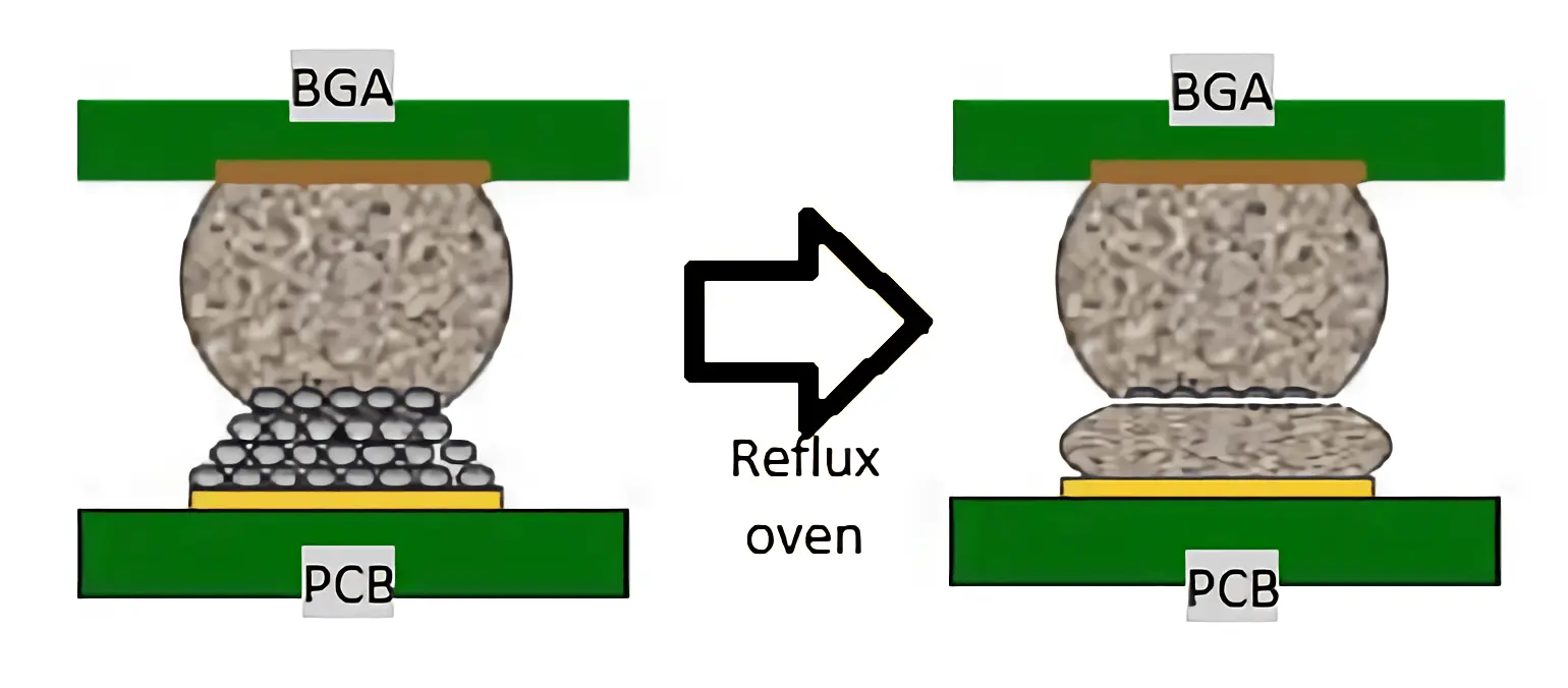
Ⅰ. What is Head-in-Pillow?
The name vividly describes the defect: the BGA solder ball rests on the solder paste deposit without fully merging—just like a head lying on a pillow. A cross-section under a microscope reveals a clear gap or a smooth interface between the ball and the reflowed paste. Such joints have almost no mechanical strength and only marginal electrical contact. Products with HIP defects may pass in-circuit test (ICT) and functional test initially, but vibration, thermal cycling, or shipping stress will eventually break the fragile connection, leading to intermittent failures or complete field returns.
Ⅱ. A Real-World Case
A factory produced intelligent control modules for automotive applications. Post-reflow X-ray sampling looked normal, and all boards passed functional testing. However, one month after shipment, customers began reporting random system freezes and signal loss. Failure analysis using 3D computed tomography (CT) revealed a classic Head-in-Pillow pattern on corner balls of the main BGA. Cross-sectioning confirmed the defect. The root cause? A peak temperature 8°C lower than the recommended reflow profile, combined with unstable nitrogen concentration inside the oven. The entire batch had to be recalled, costing tens of thousands of dollars.
Ⅲ. Why Does HIP Occur?
The mechanism is now well understood. During reflow, the PCB and the BGA package warp due to thermal expansion mismatch. When warpage is excessive, the solder ball separates from the molten solder paste. Both surfaces quickly oxidize. As the board cools and warpage recovers, the ball re-contacts the paste, but the oxide layer prevents metallurgical bonding. The result is a "head-on-pillow" appearance.
Key contributing factors include:
3.1 Material issues: Low Tg PCB or package substrate, excessive warpage.
3.2 Solder paste & profile: Insufficient flux activity, poor reflow profile (low peak temperature, short time above liquidus).
3.3 Printing & placement: Insufficient or misaligned solder paste, inaccurate component placement.
3.4 Storage & environment: Oxidized balls due to improper storage or humidity exposure.
Ⅳ. The Detection Challenge – Why 2D X-Ray Falls Short
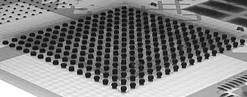
Conventional 2D X-ray inspection looks vertically through the BGA. A Head-in-Pillow joint often appears as a normal, overlapping sphere because the ball and paste are vertically aligned despite being separate. This leads to severe false negatives. To reliably detect HIP, advanced tools are necessary:
4.1 3D-CT (computed tomography) rotates the board and reconstructs the solder joint in three dimensions, clearly revealing any gap or smooth interface.
4.2 Dye-and-pry (red dye test) penetrates the defect gap, making it visible after prying open the component.
4.3 Metallurgical cross-sectioning provides the definitive evidence but is destructive and used for failure analysis.
Ⅴ. How a Professional PCBA Factory Prevents and Detects HIP
At our PCBA facility, we have embedded HIP prevention and detection into every stage of SMT production:
5.1 Strict incoming material control: We measure coplanarity of BGA packages and incoming PCBs to reject any with excessive warpage before assembly.
5.2 Optimized reflow process: For each BGA type and board thickness, we define a customized reflow profile with controlled soak ramp rate, sufficient peak temperature (typically 240–250°C for SAC305), and adequate time above liquidus (60–90 seconds). Nitrogen purging in the reflow oven minimizes oxidation.
5.3 Precision printing & placement: Automated solder paste inspection (SPI) ensures consistent volume and alignment. High-accuracy placement machines guarantee that the BGA is positioned exactly on the printed pads.
5.4 Advanced inspection: We do not rely on 2D X-ray alone. Inline high-resolution X-ray systems combined with off-line 3D-CT analysis allow us to screen every board for hidden HIP defects. Random destructive cross-section audits are also performed for process validation.
Ⅵ. Conclusion
As electronics continue to miniaturize and BGA pitches shrink, Head-in-Pillow defects represent a growing reliability risk. Detecting HIP requires more than routine AOI and 2D X-ray; it demands process discipline, optimized materials, and advanced 3D inspection capabilities. Choosing a PCBA partner that understands these nuances and invests in prevention is essential for protecting your product's reputation in the field.
Contact us today to learn how our SMT process controls and inspection strategies can ensure defect-free BGA soldering for your next project.
With 17 years of expertise in PCBA design, manufacturing, and service, KingshengPCBA is ready to help turn your ideas into reality. Feel free to contact us anytime to discuss your requirements and get a professional quotation.

Please send Email to kspcba@c-alley.com or call us through +86 13828766801 Or submit your inquiry by online form. Please fill out below form and attach your manufacturing files( PCB Gerber files and BOM List) if need quotation. We will contact you shortly.
 +86 13828766801
 kspcba@c-alley.com
 https://www.kingshengpcba.com/
 2/F, Building 6, Tangtou 3rd Industrial Zone, Tangtou Community, Shiyan Town, Baoan District, Shenzhen, China, 518108
We would also like to thank our customers for their trust and support. The company's outstanding achievements are mainly due to the loyalty of our customers, which also encourages and spurs our company to forge ahead.