* On your first PCB Assembly order!
* Up to $300 discount
 C - A L L E Y
 Home | Events | PCB | About Us | News | Contact Us
Manufacturer’s Guide
In today’s high-speed digital and RF (radio frequency) applications—from 5G base stations to millimeter-wave radar—signal integrity is non-negotiable. A slight impedance mismatch can lead to signal reflections, data corruption, and even system failure. As a PCBA manufacturer specializing in high-frequency designs, we understand that precise impedance control is the cornerstone of reliable performance. This blog explores the challenges, methodologies, and best practices for achieving tight impedance tolerances in advanced PCB fabrication.
I: Why Impedance Control Matters in High-Frequency PCBs
Impedance (measured in ohms, Ω) is the resistance a signal encounters as it travels through a transmission line (e.g., microstrips, striplines). In high-frequency circuits (≥1 GHz), maintaining consistent impedance ensures:
① Minimized Signal Loss: Reflections due to impedance mismatches can attenuate signals by 20–30%.
② Reduced EMI/RFI: Uncontrolled impedance variations act as antennas, radiating noise.
③ Compliance with Standards: IEEE, IPC-2141A, and OEMs (e.g., Huawei, Qualcomm) often mandate ±5–10% impedance tolerance. Real-World Impact: A 6-layer server motherboard with uncontrolled impedance (e.g., 50Ω target deviating to 45Ω) may suffer a 15% drop in data throughput.
II: Key Factors Influencing Impedance Control
Achieving precision requires optimizing four interdependent elements:
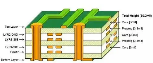
1. Dielectric Materials
① Dk (Dielectric Constant): Varies with frequency (e.g., Rogers RO4350B: Dk=3.48 at 10 GHz). Low-Dk materials (≤3.5) reduce propagation delay.
② Df (Dissipation Factor): High Df (e.g., >0.004) increases insertion loss. PTFE-based laminates (Df≈0.001) are preferred for mmWave.
③ Consistency: Thickness tolerances ≤±5% are critical; variations of 0.05mm can shift impedance by 2–3Ω.
2. Trace Geometry
① Width/Spacing: A 10μm change in trace width alters impedance by ~1Ω (for 50Ω designs).
② Cross-Sectional Shape: Trapezoidal traces (from etching) require compensation in modeling.
③ Reference Planes: Distance to ground (H) must be stable; 5% variation in H changes impedance by 3%.
III. Manufacturing Process Controls
① Etching Precision: Laser direct imaging (LDI) achieves ±3μm line width accuracy vs. ±15μm with traditional photolithography.
② Lamination Pressures: Uneven pressure causes resin flow, altering dielectric thickness.
IV. Environmental Stability
① Thermal Expansion: FR4’s Z-axis CTE (70 ppm/°C) can warp traces, while Rogers materials (30 ppm/°C) offer better stability.
② Humidity Absorption: Some substrates (e.g., FR4) absorb moisture, increasing Dk by up to 15%.
V:Advanced Techniques for Impedance Optimization
1. Simulation-Driven Design
① 3D EM Solvers: Tools like Ansys HFSS model skin effects and edge coupling at >40 GHz.
② Iterative Prototyping: Test coupons with 10+ impedance variants validate models before full production.
2. Process Innovations
① Controlled Depth Drilling: For back-drilled vias, ensuring stub lengths <10% of signal wavelength.
② Plasma Etching: Removes resin smear in HDI microvias, improving impedance continuity.
3. Testing & Validation
① TDR (Time-Domain Reflectometry): Detects impedance discontinuities with ±0.5Ω resolution.
② VNA (Vector Network Analyzer): Measures S-parameters up to 110 GHz for insertion/return loss.
Case Study: A 77GHz automotive radar PCB achieved ±3% impedance tolerance by combining Rogers RO3003 laminate, LDI etching, and post-lamination TDR testing.
VI: The Future: Impedance Control in Next-Gen PCBs
① AI-Driven Tuning: Machine learning adjusts trace widths in real-time based on TDR feedback.
② Embedded Passives: Thin-film resistors/capacitors designed to match system impedance.
③ Terahertz (THz) Readiness: Graphene-based substrates (Dk<2.5) for 300+ GHz applications.
VII: Conclusion: Precision as a Competitive Edge
For high-frequency PCBs, impedance control isn’t just a specification—it’s a system-level discipline integrating material science, process engineering, and testing rigor. At our facility, we’ve reduced impedance variability to ±2% through:
① Material partnerships with Rogers, Isola, and DuPont.
② Process certifications in IPC-6018 (HF/RF performance).
③ 100% impedance testing for mission-critical boards.
Whether you’re designing phased-array antennas or 112Gbps SerDes links, partnering with a manufacturer that masters impedance ensures your signals arrive intact—every time..
With 17 years of expertise in PCBA design, manufacturing, and service, KingshengPCBA is ready to help turn your ideas into reality. Feel free to contact us anytime to discuss your requirements and get a professional quotation.

Please send Email to kspcba@c-alley.com or call us through +86 13828766801 Or submit your inquiry by online form. Please fill out below form and attach your manufacturing files( PCB Gerber files and BOM List) if need quotation. We will contact you shortly.
 +86 13828766801
 kspcba@c-alley.com
 https://www.kingshengpcba.com/
 2/F, Building 6, Tangtou 3rd Industrial Zone, Tangtou Community, Shiyan Town, Baoan District, Shenzhen, China, 518108
We would also like to thank our customers for their trust and support. The company's outstanding achievements are mainly due to the loyalty of our customers, which also encourages and spurs our company to forge ahead.


