In PCBA manufacturing, the feeder is the direct interface through which a pick-and-place machine acquires components. Different component packaging formats have quantifiable impacts on feeder selection, setup, maintenance, and placement efficiency. This article analyzes the specific effects of three common packaging types—tape & reel, tray, and tube—on feeders.
1. Impact of Tape & Reel Packaging on Feeders
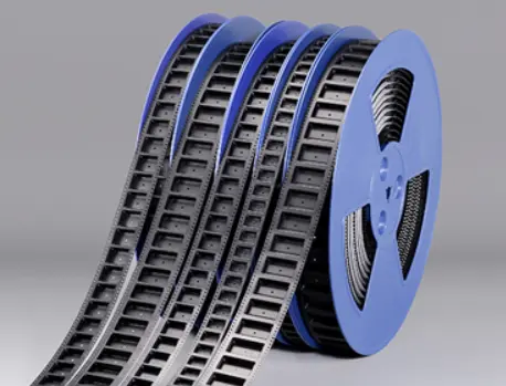
Tape & reel packaging is used for high-volume components such as resistors, capacitors, and small ICs.
1.1 Feeder Type
Tape feeders are used, which drive the carrier tape step-by-step via a sprocket or ratchet mechanism.
1.2 Key Impact Points
- A pitch deviation exceeding ±0.1mm causes misalignment in the feeder’s step travel, resulting in pickup offset by the nozzle.
- Unstable peel force of paper or plastic tape leads to jamming of the cover tape peeling mechanism, interrupting component supply.
- Mismatch between the reel hub diameter and the feeder spindle increases feeding resistance, causing stepper motor overload alarms.
1.3 Countermeasures
- Measure carrier tape pitch distance and tape thickness before warehouse entry.
- Regularly clean the sprocket and peeling blade of tape feeders.
- Use adapter bushings to eliminate reel hub gaps.
2. Impact of Tray Packaging on Feeders
Tray packaging is used for odd-form or fine-pitch components such as QFPs, BGAs, and large ICs.
2.1 Feeder Type
Tray feeders are used. These rely on multi-layer tray magazines or a single-tray platform, with the pick-and-place machine head moving to pick components.
2.2 Key Impact Points
- Tray warpage exceeding 0.2mm prevents the machine’s vision system from detecting component reference points, causing pickup failures.
- Mismatch between tray pocket dimensions and actual component body size limits the X/Y step setting of the tray feeder.
- Excessive surface resistance of anti-static trays leads to dust attraction or difficulty in component pickup due to static charge.
2.3 Countermeasures
- Conduct flatness sampling inspections on tray-packaged components.
- Set pickup position matrices based on actual component spacing during tray feeder programming.
- Use anti-static trays and regularly test surface resistance.
3. Impact of Tube Packaging on Feeders
Tube packaging is used for medium-sized components such as SOPs, SOICs, and PLCCs.
 3.1 Feeder Type
Tube feeders (stick feeders) are used. These rely on vibration or gravity to slide components from the tube into the pickup slot.
3.2 Key Impact Points
- Rough inner wall surfaces or oversized tube dimensions cause components to stack and jam, requiring resetting of the feeder vibration frequency.
- A gap exceeding 0.3mm between the tube outlet and the feeder pickup zone may cause components to tip sideways or pop out.
- In humid environments, tube-packaged components may stick due to static charge, reducing vibration feeding efficiency.
3.3 Countermeasures
- Use dedicated tubes with dimensional tolerance ≤0.1mm relative to component body size.
- Before placing each batch of tube-packaged materials, inspect tube ends for burrs and deformation.
- Equip tube feeders with adjustable vibration amplitude to accommodate different component weights.
Summary
Different component packaging directly determines the feeder type and its operating parameters. Tape & reel packaging tests the mechanical indexing accuracy of feeders. Tray packaging relies on the positional coordination between the feeding platform and vision system. Tube packaging requires proper vibration control and guide structure matching from the feeder.
With 17 years of expertise in PCBA design, manufacturing, and service, KingshengPCBA is ready to help turn your ideas into reality.
Feel free to contact us anytime to discuss your requirements and get a professional quotation.
 C - A L L E Y
 +86 13828766801
 kspcba@c-alley.com
 https://www.kingshengpcba.com/
 2/F, Building 6, Tangtou 3rd Industrial Zone, Tangtou Community, Shiyan Town, Baoan District, Shenzhen, China, 518108


