Impact of Different PCB Substrates (FR-4, Aluminum, Ceramic, Polyimide) on Assembly
 C - A L L E Y
Home | Events | PCB | About Us | News | Contact Us
In
PCBA manufacturing, substrate selection directly affects assembly processes, equipment parameters, and yield rates. This article analyzes the specific impacts of four common substrate materials on assembly from a production perspective.
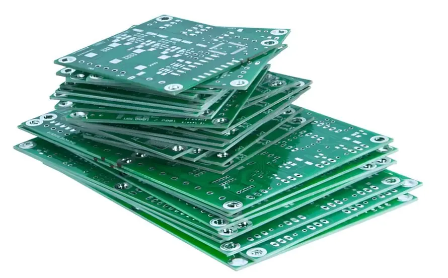
1. FR-4: Most Common but Thermal Stress Must Be Controlled
FR-4 is a glass-reinforced epoxy laminate, accounting for over 70% of the PCBA market.
 1.1 Impact on Soldering Process
The glass transition temperature (Tg) of FR-4 typically ranges from 130°C to 170°C. Lead-free reflow peak temperatures reach 245–260°C, which is close to FR-4’s thermal decomposition temperature (Td). Excessive reflow cycles or prolonged high-temperature exposure can cause Z-axis expansion and delamination (blow-out) or reduce copper foil adhesion.
1.2 Limitations on Placement Accuracy
FR-4’s coefficient of thermal expansion (CTE) in the X-Y direction is approximately 14–17 ppm/°C, which does not match that of ceramic-packaged components (CTE approx. 6–8 ppm/°C). When placing large BGAs or 01005 components, shear stress generated during the cooling phase of reflow can cause solder joint cracking or solder ball detachment.
2. Aluminum-Core Board: Thermal Advantage but Higher Process Demands
Aluminum-core boards consist of an aluminum base, a dielectric layer, and a copper foil. They are mainly used for LEDs and power modules.
2.1 Prerequisites for Assembly: Pre-baking and Dedicated Fixtures
The dielectric layer of aluminum-core boards is typically epoxy or polyimide, which is prone to blistering during reflow if moisture is absorbed. Pre-baking at 125°C for 4–6 hours is required before assembly. Due to rapid heat absorption during placement, heated-bottom fixtures must be used to prevent board warpage that can cause component shift.
2.2 Differences in Reflow Soldering Profile
Aluminum-core boards have high thermal conductivity (1–3 W/m·K, compared to 0.3 W/m·K for FR-4). Oven temperature settings should increase lower zone temperatures by 5–10°C, or reduce conveyor speed by 20%, to ensure solder melting without overheating the dielectric layer.
3. Ceramic Substrate: High Reliability but Brittle and Requires Strict Cleaning
Ceramic boards (Al₂O₃, AlN, Si₃N₄) are used in high-frequency, high-power, and high-hermeticity applications.
3.1 Placement Challenges: Brittle Material and Thermal Expansion Matching
Ceramic boards are hard and non-ductile. Placement pressure exceeding 0.5N can cause board cracking, especially for thicknesses below 0.38mm. A placement head with pressure feedback and slow placement speed is required. Due to the low CTE of ceramic (approx. 4–7 ppm/°C), CTE mismatch stress must be verified when placing large FR-4 or metal components.
3.2 Special Soldering Process Requirements
AlN ceramic is susceptible to hydrolysis. Exposure to air for 48 hours can generate Al(OH)₃, affecting pad solderability. Boards should be assembled within 4 hours of opening the package. Vacuum reflow or nitrogen-protected reflow is typically used to keep solder joint voiding below 5%.
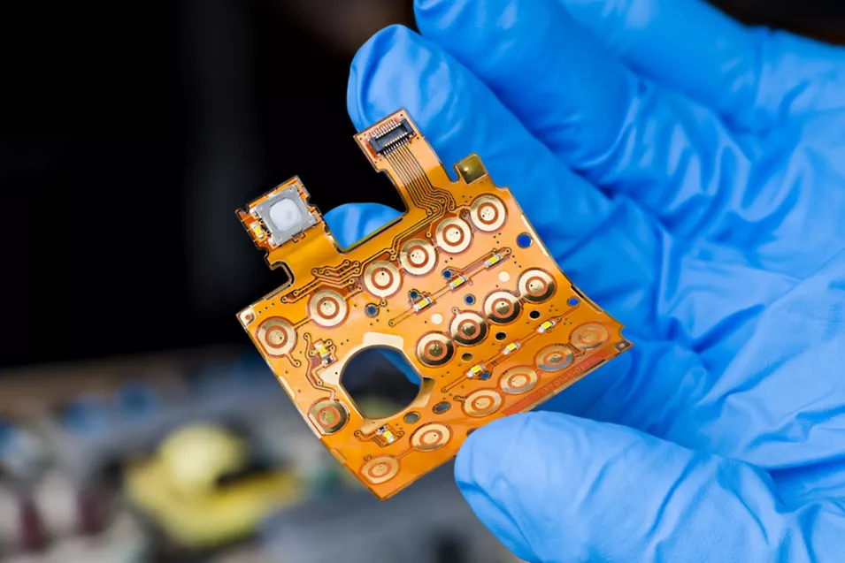
4. Polyimide: Flexible but Requires Low Temperature and Support Carrier
Polyimide (PI) is used for flexible printed circuits (FPCs) with thicknesses of 0.05–0.2mm.
 4.1 Assembly Pain Point: Deformation Control
PI film softens at the 260°C reflow temperature, causing component shift or tombstoning. Low-temperature solder paste (SnBi or SnBiAg, melting point 138–170°C) is typically used, with peak temperature kept below 200°C. During placement, magnetic clamps or high-temperature tape must be used to fix the FPC onto a carrier board to ensure printing and placement accuracy.
4.2 Baking and Shelf Life
Polyimide has higher moisture absorption than FR-4 (0.5% vs. 0.2%). After 24 hours of air exposure, baking at 125°C for 2 hours is required. If boards are not baked before reflow, the "popcorn effect" can cause delamination between copper foil and PI.
Summary: Substrate-to-Assembly Recommendation Table
Substrate & Recommended Assembly Process & Key Risks
- FR-4 -> Standard lead-free reflow, Tg≥170°C preferred -> High-temperature delamination, CTE mismatch for large components
- Aluminum-core -> Enhanced lower-zone heating, pre-baking, fixture support -> Warpage, dielectric blistering
- Ceramic -> Nitrogen or vacuum reflow, quick assembly after opening, slow placement -> Board cracking, solder voids, AlN hydrolysis
- Polyimide -> Low-temperature solder paste, carrier fixation, strict moisture control -> Deformation, delamination, component shift
With 17 years of expertise in PCBA design, manufacturing, and service, KingshengPCBA is ready to help turn your ideas into reality.
Feel free to contact us anytime to discuss your requirements and get a professional quotation.

 +86 13828766801
 kspcba@c-alley.com
 https://www.kingshengpcba.com/
 2/F, Building 6, Tangtou 3rd Industrial Zone, Tangtou Community, Shiyan Town, Baoan District, Shenzhen, China, 518108


