Precautions for Crimp Connector Assembly in PCBA Processing
 C - A L L E Y
Home | Events | PCB | About Us | News | Contact Us
In PCBA processing, the crimping process for connectors is often treated as a "trivial matter," but it is precisely these details that determine the reliability and lifespan of the entire board. Many people assume that crimping is simply a matter of inserting a terminal into a hole and pressing down, leading to hidden issues such as poor contact, loose connections, and even board layer damage. Today, let's discuss several key points that must be observed during crimp connector assembly.
 I. Choose the right crimping tool—don't compromise
Crimping is not something you can do casually with a pair of pliers. Different connector specifications and wire gauges require specific crimping heads and pressure parameters. Using non-specialized tools most easily leads to inconsistent crimp heights, terminal deformation, or core wire breakage.
Recommendation: Strictly follow the crimping tool models recommended by the connector manufacturer, and regularly calibrate crimp height and pull force values. A qualified crimped terminal should pass standard pull force tests.
II. Strip length must be precise—don't rely on guesswork
If the strip length is too long, excessive conductor exposure can cause short circuits; if too short, the crimp area cannot secure the core wire, resulting in insufficient pull force. Different connector design drawings specify the strip length, typically ranging from 3–8 mm.
Operation tips: Use a strip machine or specified stripping pliers to avoid damaging copper strands. After stripping, check for broken strands or residual insulation. If even one broken strand is found, the wire must be redone.
III. Inspect conductor condition before crimping
This step is overlooked in many factories. If the copper strands are oxidized, blackened, loose, or contaminated with solder (yes, some people dip crimp wires in solder), the contact resistance will significantly increase after crimping, leading to overheating and burnout over time.
Correct practice: After stripping, visually inspect that the copper strands are bright, undamaged, and free of oxidation. Multi-strand wires should remain twisted and not splayed. Never tin the wire ends before crimping—solder creeps over time, causing the crimp point to loosen.
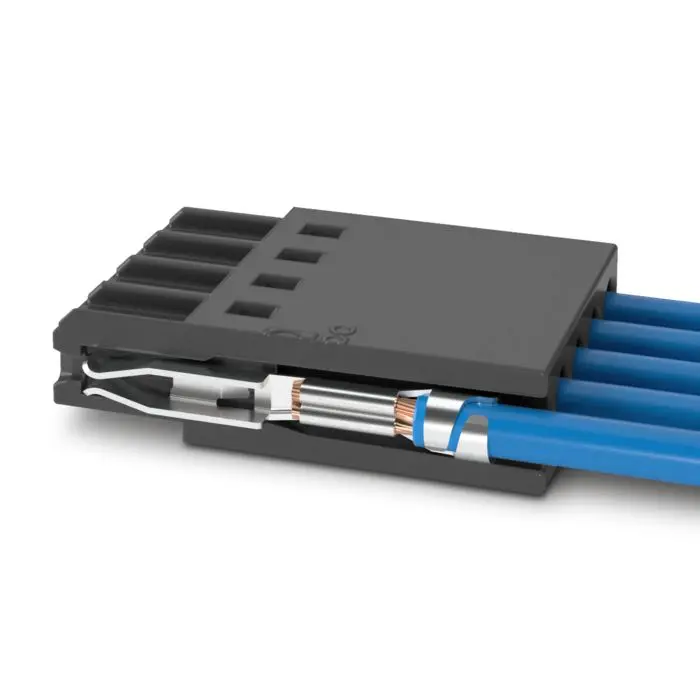
IV. Align the crimp position correctly to avoid "flying wire" and "insulation inclusion"
The crimp area is typically divided into two sections: one for crimping the conductor (copper strands) and one for crimping the insulation. Common defects are:
Conductor exposed too long, crimping onto the insulation → conductor not securely clamped.
Insulation pressed into the conductor area → poor core wire contact.
Judgment standard: After crimping, the inspection window should show the conductor end just emerging or slightly shorter than the conductor crimp area, with the insulation just contacting the front end of the insulation crimp section.
V. Perform pull force testing after crimping
It's not a question of whether to test, but of sampling frequency. For batch production, it is recommended to randomly test at least 5 samples per shift, per crimping machine, and per terminal type, recording the pull force values. If the pull force falls below the lower limit specified in the connector datasheet, the entire batch needs re-evaluation.
Common causes of insufficient pull force: excessive crimp height, incorrect wire gauge selection, tool wear.
VI. Pay attention to alignment and floating height of the connector on the PCB
When press-fit connectors are inserted into the PCB, many are interference-fit and require a dedicated pressing tool. Pressing by hand or hammering can easily cause floating height, tilting, or even cracking the copper-plated through-holes inside the PCB.
Operation standards:
- Use a pressing fixture to ensure the connector is perpendicular to the board surface.
- Control pressing speed to avoid impact loads.
- After pressing, check that the connector base fits tightly against the board surface with no gaps.
VII. Don't ignore temperature and humidity environment
The crimp terminal and PCB hole form a tight mechanical contact that is sensitive to the environment. Connectors stored for too long in humid or sulfur-containing environments may have oxidized contact surfaces. It is recommended to keep assembly shop humidity between 40%–60%. Once the connector packaging is opened, use it as soon as possible; reseal any unused connectors for storage.
Conclusion
Crimping may seem simple, but it is a link highly prone to issues in the PCBA reliability chain. From tool selection, wire stripping, conductor condition, to pull force verification—every step deserves serious attention.
Shenzhen Kingsheng Technology Co., Ltd. has rich experience and a professional technical team in PCBA.
Contact KingshengPCBA today to request a quote or discuss your PCBA project.

 +86 13828766801
 kspcba@c-alley.com
 https://www.kingshengpcba.com/
 2/F, Building 6, Tangtou 3rd Industrial Zone, Tangtou Community, Shiyan Town, Baoan District, Shenzhen, China, 518108


