* On your first PCB Assembly order!
* Up to $300 discount
 C - A L L E Y
 Home | Events | PCB | About Us | News | Contact Us
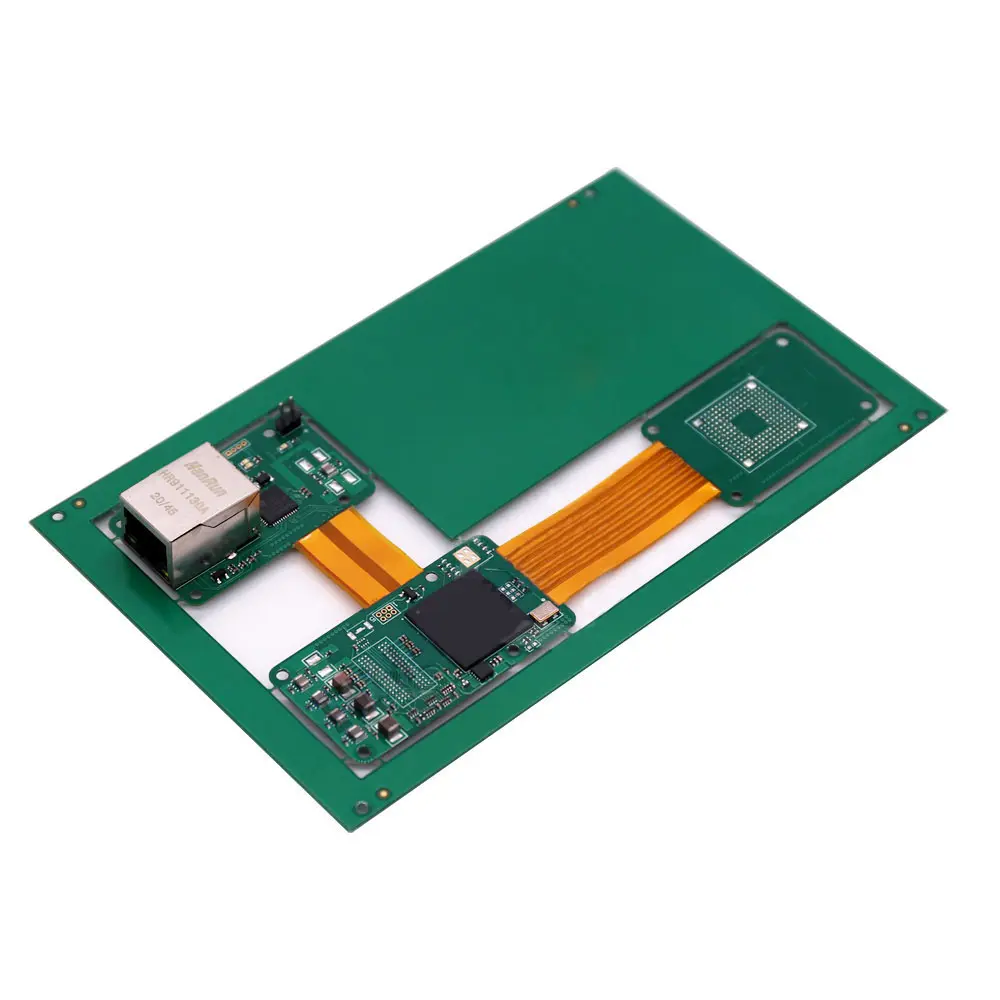
With the trend towards miniaturization and high density in electronic products, flexible/rigid-flex boards have become a core carrier for medical devices, wearable devices, aerospace, and high-end consumer electronics. However, many engineers encounter unexpected assembly challenges when first working with these boards. Today, we delve into these technical pain points and their solutions.
Four Major Assembly Challenges and Their Solutions
I.Positioning and Clamping Difficulties Due to the Non-planar Characteristics of the Board Material
Challenge Analysis: Traditional rigid PCBs can be placed flat during SMT assembly, but the flexible parts of rigid-flex boards can warp unpredictably at high temperatures, leading to component placement deviations. The bending characteristics of the flexible parts make conveyor belt transport difficult and prone to positional shifts during wave soldering.
Solution:
1.Dedicated Carrier Design: Use specially designed fixtures to support the flexible areas, maintaining the flatness of the entire board during assembly. The carrier material should be selected based on its low coefficient of thermal expansion (CTE), such as aluminum-silicon alloy or ceramic-filled composite materials.
2.Segmented support technology: Provide targeted support for rigid and flexible areas of different thicknesses to avoid stress concentration.
3.Optical positioning optimization: Add high-contrast Fiducial markings to the rigid area, ensuring accurate positioning even if the flexible area deforms.
II.Mismatch in the coefficient of thermal expansion (CTE) of heterogeneous materials
Challenge analysis: The CTE of the flexible substrate (usually polyimide) is approximately 30-50 ppm/℃, while the CTE of the rigid part of FR-4 is only 12-18 ppm/℃. This difference generates significant thermal stress during reflow soldering, leading to interface delamination and solder joint cracking.
Solutions:
1.Stepped Reflow Temperature Profile: Employ a gentler profile with extended preheating time and lower peak temperature (recommended 230-240℃) to reduce thermal shock.
2.Material Interface Enhancement: Uses reinforced adhesive sheets, such as 3M™ 2929 high-toughness adhesive, at the rigid-flexible interface.
3.Special Pad Design: Uses teardrop-shaped pads and anchor points in the rigid-flexible transition area to distribute stress.
III. Challenges in Component Assembly and Protection in Flexible Areas
Challenge Analysis: Flexible substrates cannot withstand the insertion pressure of traditional through-hole components, and flexible parts are susceptible to mechanical damage during assembly.
Solutions:
1.Layout Optimization: Place all through-hole components and large BGA devices in rigid areas.
2.Local Reinforcement Technology: Add stainless steel or polyimide reinforcing sheets to the back of component mounting points in flexible areas, with a recommended thickness of 0.1-0.2mm.
3.Selective Coating: Use flexible conformal coating for localized protection of solder joints in flexible areas, avoiding the use of rigid coatings.
IV. Risk Control of Multiple Reflows and Rework
Challenge Analysis: Rigid-flex boards often require double-sided mounting, meaning they undergo two reflow processes. Repeated heating of flexible materials may lead to interlayer delamination or degradation of mechanical properties.
Solutions:
1.Assembly Sequence Optimization: Mount the side with fewer components first, using low-temperature solder paste (e.g., Sn-Bi alloy, melting point 138℃).
2.Local Shielding Technology: During secondary reflow, use thermal insulation material to locally protect the soldered surfaces.
3.Precise Rework Temperature Control: Use an infrared thermal imager to monitor the temperature of the rework area in real time, ensuring that the flexible area does not exceed its glass transition temperature (typically around 250℃).
Advanced Techniques: Process Verification and Quality Inspection
*Pre-bending Test: Perform simulated bending tests on the board before formal assembly to verify the reliability of the design.
*X-ray Delamination Scanning: Pay special attention to the lamination quality at the rigid-flex interface.
*Micro-section Analysis: Regularly perform destructive testing on solder joints and interfaces in transition areas.
Conclusion
Assembling rigid-flex boards is indeed much more complex than traditional PCBs, but this is precisely its value—through precise process control, we can achieve unprecedented design freedom within limited space. Remember, the key to success lies in the close collaboration between early-stage design and later-stage process. Every challenge is an opportunity for process innovation, which is the most exciting part of the electronics manufacturing industry.
With 16 years of expertise in PCBA design, manufacturing, and service, KingshengPCBA is ready to help turn your ideas into reality. Feel free to contact us anytime to discuss your requirements and get a professional quotation.

Please send Email to kspcba@c-alley.com or call us through +86 13828766801 Or submit your inquiry by online form. Please fill out below form and attach your manufacturing files( PCB Gerber files and BOM List) if need quotation. We will contact you shortly.
 +86 13828766801
 kspcba@c-alley.com
 https://www.kingshengpcba.com/
 2/F, Building 6, Tangtou 3rd Industrial Zone, Tangtou Community, Shiyan Town, Baoan District, Shenzhen, China, 518108
We would also like to thank our customers for their trust and support. The company's outstanding achievements are mainly due to the loyalty of our customers, which also encourages and spurs our company to forge ahead.


