* On your first PCB Assembly order!
* Up to $300 discount
 C - A L L E Y
 Home | Events | PCB | About Us | News | Contact Us
As signal rates enter the GHz era, PCB design has evolved from simple to complex. Mastering the following key technologies is crucial for successful design.
I. Practical Essentials of Transmission Line Theory and Loss Control
When signal rates exceed 100MHz, PCB traces must be treated as transmission lines. Characteristic impedance (Z0) control is fundamental, with common single-ended impedance (50Ω) and differential impedance (100Ω).
Losses primarily arise from three aspects:
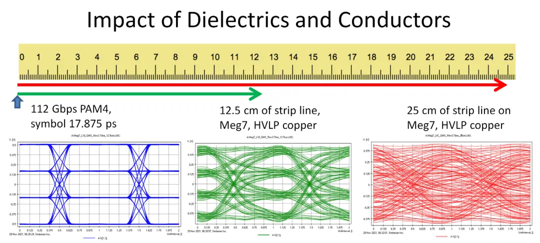
* Conductor Loss: As frequency increases, the skin effect intensifies.
Solution: Employ low-roughness copper foil (such as HVLP); reducing surface roughness can decrease high-frequency loss by 30%.
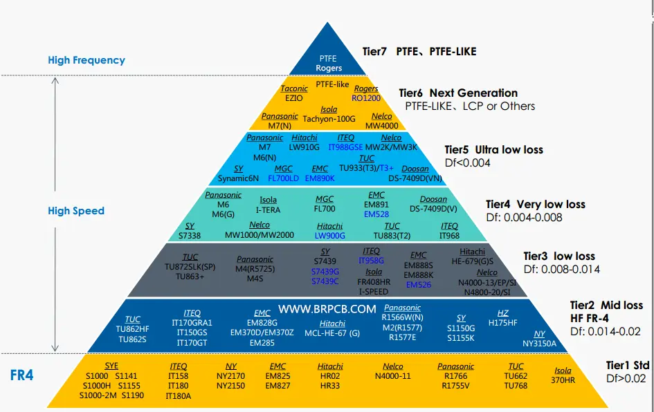
* Dielectric Loss: Determined by the substrate material, a lower dissipation factor (Df) is preferred. The Df of FR-4 is approximately 0.02, while high-end materials like Rogers 4350B have a Df of only 0.0037.
* Reflection Loss: Controlled through strict impedance matching, impedance deviation should be maintained within ±10%.
Practical Tip: For rates above 25 Gbps, prioritize low-loss materials such as Megtron 6 and the Rogers series, and employ back-drilling techniques to minimize stub effects.
II. Collaborative Suppression Strategies for Crosstalk, Reflection, and EMI
Crosstalk Control Triad:
1. Spacing Rules: Adhere to the 3W rule (line spacing ≥ 3 times the line width); use 5W spacing between sensitive signals.
2. Reference Plane Integrity: Ensure a complete reference plane beneath the trace and avoid crossing splits.
3. Termination Optimization: Source-series termination (most common), parallel termination, or Thevenin termination can be used.
Key points for reflection suppression:
1. Maintain impedance continuity: Add return vias at the through-holes, and gradually transition where the linewidth changes.
2. Reduce stub length: In particular, for unused portions of connectors and vias, stub length must be less than 10 mil for speeds above 25Gbps.
Practical methods for EMI suppression:
1. Stack-up Design: High-speed signal layers are sandwiched between two ground planes to form a "sandwich" structure.
2. Shielding Techniques: For strong radiation sources such as clocks, a stripline structure of "ground-signal-ground" is used.
3. Filter Deployment: A π-type filter network is arranged at the connector to absorb common-mode noise.
III. Scientific Decision-Making Framework for RF PCB Material Selection
Material selection is evaluated from four dimensions.
1. Dk (Dielectric Constant) Stability
* Dk fluctuation should be less than 5% when frequency changes.
* A small temperature coefficient ensures stable performance when the ambient temperature changes.
* Rogers RO4350B exhibits excellent performance in this regard.
2. Loss Performance Classification
* General applications: FR-4 (Df≈0.02)
* Moderate requirements: Isola 370HR (Df≈0.01)
* High-frequency applications: Rogers RO4000 series (Df<0.004)
3. Thermal Management Capability
* High-power RF circuits require materials with high thermal conductivity.
* Ceramic-filled PTFE materials have better thermal conductivity than traditional FR-4.
4. Process Compatibility
* Consider the matching degree between the material and the PCB manufacturer's process.
* Although PTFE materials have excellent performance, they are difficult to process and costly.
Cost Balancing Recommendation: Employ a hybrid stack-up design, utilizing high-performance materials for the radio frequency sections and FR-4 for the digital sections, which ensures performance while controlling costs.
Conclusion: Systematized Design Thinking
The key to successful high-speed PCB design lies in forward-looking simulation and collaborative optimization. Before the layout process, conduct pre-simulation using SI/PI tools and establish design rules; and After the layout is completed, conduct detailed verification to form a closed-loop process of "design - simulation - optimization". Remember: There is no perfect single solution; there is only the best balance point tailored to the specific application scenario.
With 16 years of expertise in PCBA design, manufacturing, and service, KingshengPCBA is ready to help turn your ideas into reality. Feel free to contact us anytime to discuss your requirements and get a professional quotation.

Please send Email to kspcba@c-alley.com or call us through +86 13828766801 Or submit your inquiry by online form. Please fill out below form and attach your manufacturing files( PCB Gerber files and BOM List) if need quotation. We will contact you shortly.
 +86 13828766801
 kspcba@c-alley.com
 https://www.kingshengpcba.com/
 2/F, Building 6, Tangtou 3rd Industrial Zone, Tangtou Community, Shiyan Town, Baoan District, Shenzhen, China, 518108
We would also like to thank our customers for their trust and support. The company's outstanding achievements are mainly due to the loyalty of our customers, which also encourages and spurs our company to forge ahead.


