How IPC standards shape the top-notch PCB assembly processes?
 C - A L L E Y
Home | Events | PCB | About Us | News | Contact Us
In the field of PCBA manufacturing, IPC standards are not optional suggestions, but rather the technical baseline and quality passport that determine the reliability of a product. This article will directly address the core issues and analyze how IPC standards specifically affect each manufacturing process.
I. Design Phase: How IPC Eliminates 50% of Potential Defects in Advance
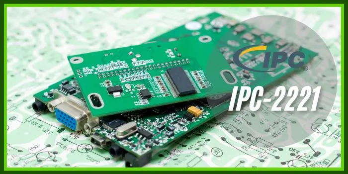
IPC-2221 Series (Design Foundation Standard)
The latest version of IPC-2221E (2023), has significantly updated the calculation methods for creepage distance and clearance, introducing a more scientific voltage peak method to replace the old empirical table lookup method. This directly affects the layout safety of high-voltage PCBAs (such as those in new energy vehicles and photovoltaic inverters), and can accurately prevent arc breakdown.
 IPC-7251/7351 (Hole and Pad Design)
It provides globally-accepted component pad pattern libraries. Utilizing its recommended Density Levels (Level A/B/C) can systematically address issues like tombstoning, component shifting, or insufficient solder during reflow soldering. For example, for 01005 ultra-miniature components, the Class C (High Density) recommended land pattern must be adopted; otherwise, the yield rate will plummet.
IPC-2152 (Determining Current-Carrying Capacity)
This is the core standard that replaces the old current-carrying capacity charts in IPC-2221. It establishes a mathematical model based on complex factors such as copper thickness, temperature rise, inner/outer layers, and adjacent traces. Practical application: Designing a motor drive board that handles high current, using IPC-2152 to calculate the minimum trace width for 1oz copper thickness and 10°C temperature rise, which can save 20-30% of routing space compared to traditional empirical values, or significantly reduce the risk of overheating.
II. Process and Materials: Quantitatively Controlling the Formation of Each Solder Joint
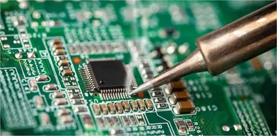
IPC-J-STD-001 (Soldering Requirements)
This standard is not only for evaluating the quality of solder joints but also serves as a process control manual. It explicitly specifies:
Solder Alloy Purity: Must comply with ANSI/J-STD-006 requirements, with impurity limits for elements such as lead and zinc specified precisely to the ppm level.
Flux Type Management: For different cleanliness requirements (R, RMA, RA, OA), it specifies test methods for residual ionic contamination (e.g., IPC-TM-650 2.3.28).
Soldering Temperature Profile Parameters: It not only provides ranges but also defines the attachment method and location for measuring thermocouples to ensure data comparability.
 IPC-7527 (Stencil Design Guidelines)
Stencil apertures are not simply scaled down proportionally. The standard provides specific dimensional ratios for stepped and trapezoidal apertures for fine-pitch QFPs and BGAs. For example, for a 0.4mm pitch BGA, a Circle-Square aperture is recommended, with precise area ratio and aspect ratio calculation formulas provided to ensure a paste release rate greater than 85%.
III. Inspection and Reliability: From "Subjective Judgment" to "Objective Measurement"
IPC-A-610 (Acceptability of Electronic Assemblies)
Its value lies in transforming qualitative descriptions into quantitative measurements.
Chip component side solder width: must be ≥ 50% of the component termination height (W) or pad width (P) (whichever is smaller), with clear illustrations provided.
BGA solder joint void acceptance criteria: It strictly stipulates that the area of a single void shall not exceed 25% of the solder ball's projected area, and the void location must not be at the interface between the solder joint and the PCB pad (stricter requirements for Class I products).
Three-Point Coplanarity: For connectors and large QFPs, the bottom of the pins must lie on the same plane, with a tolerance typically of 0.1mm, and measured using professional fixtures.
 IPC-6012 (Qualification and Performance Specification for Rigid Printed Boards)
It is divided into three performance classes: 1/2/3.
Key differences between Class 2 (Commercial) and Class 3 (High Reliability): For through-holes, Class 3 requires 100% backlight inspection (IPC-6012 3.6.2) to ensure uniform copper plating on the hole walls and no voids; it also requires more stringent thermal stress testing (288°C solder pot, 10 seconds floating solder, repeated 3 times) with no delamination or hole wall fracture.
Conclusion
The ultimate value of deeply applying IPC standards lies in transforming the manufacturing process from an art reliant on the "experience” into a predictable, replicable, and optimizable engineering system based on data and science. It is not an exclusive document for the quality department but rather a "manufacturing gene" that needs to be understood and internalized by everyone in design, process, production, procurement, and quality. For companies aiming to penetrate high-barrier markets such as automotive electronics, aerospace, and high-end medical equipment, the depth of mastery and rigor of execution of IPC standards directly equates to the breadth of their technological moat and the height of their product premium.
With 16 years of expertise in PCBA design, manufacturing, and service, KingshengPCBA is ready to help turn your ideas into reality. Feel free to contact us anytime to discuss your requirements and get a professional quotation.

 +86 13828766801
 kspcba@c-alley.com
 https://www.kingshengpcba.com/
 2/F, Building 6, Tangtou 3rd Industrial Zone, Tangtou Community, Shiyan Town, Baoan District, Shenzhen, China, 518108


