
Power banks are an excellent power source when you're away from home. This convenient and portable device can charge your phone multiple times. Although power banks have many uses, this article is tailored for those who manufacture power bank circuit boards or those interested in building their own power banks.
What is a Power Bank Circuit Board?
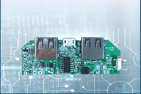
A power bank printed circuit board (PCB) is a silicon chip that serves as the mainboard of the power bank. When assembled, a power bank PCB has power input and output points, capacitors, diodes, and other components that enable it to store charge in the batteries and discharge it when needed.
The power bank circuit board is crucial for the device's functionality. It acts as a central mediator between the batteries and your mobile phone, making it the most essential component of the power bank.
Types of Power Bank Circuit Boards
1. Single-Layer PCB
This is the most common type of PCB and is often the most sensible choice for power banks. A basic power bank typically includes a micro-USB female connector, various connectors, a couple of LEDs (to indicate the remaining battery and charging status), a few resistors, capacitors, and diodes. These components can be easily assembled on a single-sided PCB, which helps reduce costs.
2. Rigid PCB
Using a rigid PCB in power banks makes perfect sense because it can withstand heavy loads. Power banks go through rigorous charge and discharge cycles, so creating a charge/discharge module with a rigid PCB is a smart idea.
A power bank's PCB assembly generally includes a shell, battery, and circuit board. The power supply shell provides protection, aesthetic appeal, and other functionalities. The battery cell and circuit components mainly consist of a lithium core capacity indication circuit, a charging management circuit, a Battery Management System (BMS), and a DC-DC boost circuit.
The lithium core capacity indication circuit includes a voltage monitoring chip and an electronic circuit. The charging management circuit utilizes a battery charging management chip. The BMS features overcharge protection, over-discharge protection, and over-temperature protection. The DC-DC boost circuit employs an integrated chip for DC switch control, maximizing the release of lithium core capacity within safe limits to power various digital devices.
Please send Email to kspcba@c-alley.com or call us through +86 13828766801 Or submit your inquiry by online form. Please fill out below form and attach your manufacturing files( PCB Gerber files and BOM List) if need quotation. We will contact you shortly.
 +86 13828766801
 kspcba@c-alley.com
 https://www.kingshengpcba.com/
 2/F, Building 6, Tangtou 3rd Industrial Zone, Tangtou Community, Shiyan Town, Baoan District, Shenzhen, China, 518108
We would also like to thank our customers for their trust and support. The company's outstanding achievements are mainly due to the loyalty of our customers, which also encourages and spurs our company to forge ahead.


