Design Pain Points and Operational-Level Solutions for Medical Ventilator Control Board PCBA
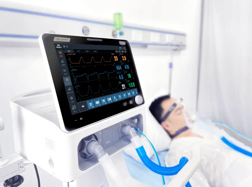
As a Class III life-support device, the
ventilator PCBA must maintain pressure control accuracy (±0.5 cmH₂O) in extreme electromagnetic environments, achieve operational noise below 30 decibels, and meet a mean time between failures (MTBF) of over 10 years. Based on practical experience serving multiple ventilator OEMs, this article deconstructs the core design pain points and provides actionable manufacturing-level solutions.
 I. The Isolation Paradox Between Analog Front-End and High-Power Drive
1.1 Pain Point: "Ground Plane Contamination" in the Signal Chain
I. The Isolation Paradox Between Analog Front-End and High-Power Drive
1.1 Pain Point: "Ground Plane Contamination" in the Signal Chain
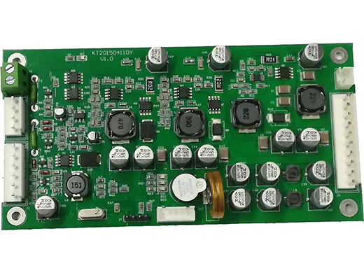
A ventilator main control board typically includes microvolt-level pressure sensor signals and a fan driver circuit exceeding 50 watts. During continuous operation in an ICU environment, sudden changes in high current easily couple into the analog front-end through the common ground return path, causing ADC sampling drift. The traditional "one-size-fits-all" copper pour method fails to resolve return path conflicts. Distorted sensor data directly leads to erroneous pressure control logic, which is clinically unacceptable.
1.2 Solution: Implement a "Segmented Single-Point Grounding" Strategy
Strictly enforce an
<br />. During the PCB design review phase, mandate that the design team physically partition the PCB into a high-precision analog zone (sensors), a digital processing zone (MCU), and a noise source zone (motor driver). Require customers to physically separate power ground (PGND) and analog ground (AGND) in the layout, connecting them at a single point via a ferrite bead or a 0-ohm resistor, ideally located at the power entry point or beneath the ADC. Furthermore, for boards with six or more layers, ensure the second layer is a complete ground plane to absorb high-frequency noise through the parasitic capacitance of the multilayer board.
II. Uncontrolled Thermal and Mechanical Stress in Extreme Environments
2.1 Pain Point: "Hidden Open Circuits" Caused by CTE Mismatch
Ventilators often operate continuously, 24 hours a day, 7 days a week. The temperature rise of the motor driver chip and the Coefficient of Thermal Expansion (CTE) mismatch with the PCB substrate material create shear stress on
BGA-packaged MCUs or power management ICs during thermal cycling. The micro-cracks in solder joints caused by this stress may pass
ICT testing but can lead to intermittent failures in a clinical environment with high humidity and vibration. This is the most insidious defect in SMT assembly.
2.2 Solution: High-Tg Materials and Thermal Path Design
Operations must strictly control material selection. For continuously operating models, mandate the elimination of standard FR-4 (Tg 130-140°C) and uniformly adopt
high TG170 or higher heat-resistant substrates or ceramic-filled boards to stabilize the dielectric constant. On the
SMT process side, add
thermal via arrays beneath high-power devices to conduct heat to the copper area on the backside. Additionally, we recommend applying
thermal gel filling in high-heat areas. This not only improves heat dissipation efficiency by 5-10% but also absorbs vibration energy through physical buffering, reducing the risk of lead cracks.
 III. The "Double Trap" of Conformal Coating Application
3.1 Pain Point: Electrochemical Corrosion and Sensor Blockage
III. The "Double Trap" of Conformal Coating Application
3.1 Pain Point: Electrochemical Corrosion and Sensor Blockage
The high-humidity environment generated by the ventilator’s humidifier easily forms a water film on the PCBA surface. This leads to electrochemical migration between precision resistors due to ions and bias voltage, causing insulation failure. However, conformal coating is a double-edged sword: if the application process is improper, the flowing coating can seep into the reference cavity or micro-holes of the pressure sensor, directly rendering the sensor completely insensitive. Conversely, if masking is incomplete to avoid the sensor, edge creep corrosion becomes unavoidable.
3.2 Solution: Selective Automated Spraying and Vacuum Encapsulation
Decisively eliminate manual brushing or simple spraying and invest in
selective automated spraying equipment. Use high-precision masking fixtures to protect connectors, test points, and sensor vent holes, ensuring a uniform coating thickness (typically 0.2-0.5mm) that never enters prohibited areas. For hard-to-spray areas like the underside of sensors and BGAs, adopt a
vacuum encapsulation process. Use negative pressure to draw nano-coating materials into the gaps, completely eliminating residual dead corners.
IV. Lack of Stringent Zero-Defect Traceability
4.1 Pain Point: "Black Box" Production and Material Substitution
Medical regulations require PCBA traceability throughout a 10-year lifecycle. In practice, we find that many cost-driven factories use refurbished components or unregistered substitute materials, causing devices to fail clinical alarms or EMC testing. Without traceability to original batch numbers, production environment parameters, and specific operator records, OEMs cannot pass FDA or NMPA audits.
4.2 Solution: Build a Digital MES Monitoring System
Establish a "
High-Reliability (Hi-Rel)" manufacturing process. All materials used in production must undergo incoming quality control (IQC) inspection and be logged into the MES system. Prohibit the use of components nearing end-of-life. On the SMT line, perform real-time monitoring of solder paste printing and reflow oven temperature profiles, linking the data to the PCB's unique serial number. The testing phase must include
100% AOI + X-Ray (for BGAs) + functional testing. The
FCT (Functional Circuit Test) fixture must simulate the ventilator's full operating range of 4-20 cmH₂O pressure. All test data must be uploaded in real-time, ensuring that every single board can be traced back to specific material batches and equipment parameters.
 +86 13828766801
 kspcba@c-alley.com
 https://www.kingshengpcba.com/
 2/F, Building 6, Tangtou 3rd Industrial Zone, Tangtou Community, Shiyan Town, Baoan District, Shenzhen, China, 518108


