Garbage Truck Controller PCBA: Key Technical Points from Component Selection to Mass Production
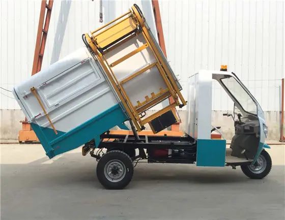
The garbage truck controller is the core electrical component of sanitation vehicles. It controls multiple hydraulic actuators including garbage compaction, lifting and tipping, tailgate opening/closing, and push plate movement. With the implementation of China National Emission Standard VI and the growing adoption of new energy sanitation vehicles, garbage truck controllers now demand higher reliability, noise immunity, and functional integration from their PCBAs. From a
PCBA manufacturing perspective, this article covers practical points in component selection, PCB design,
SMT processes, and
conformal coating for garbage truck controller boards.
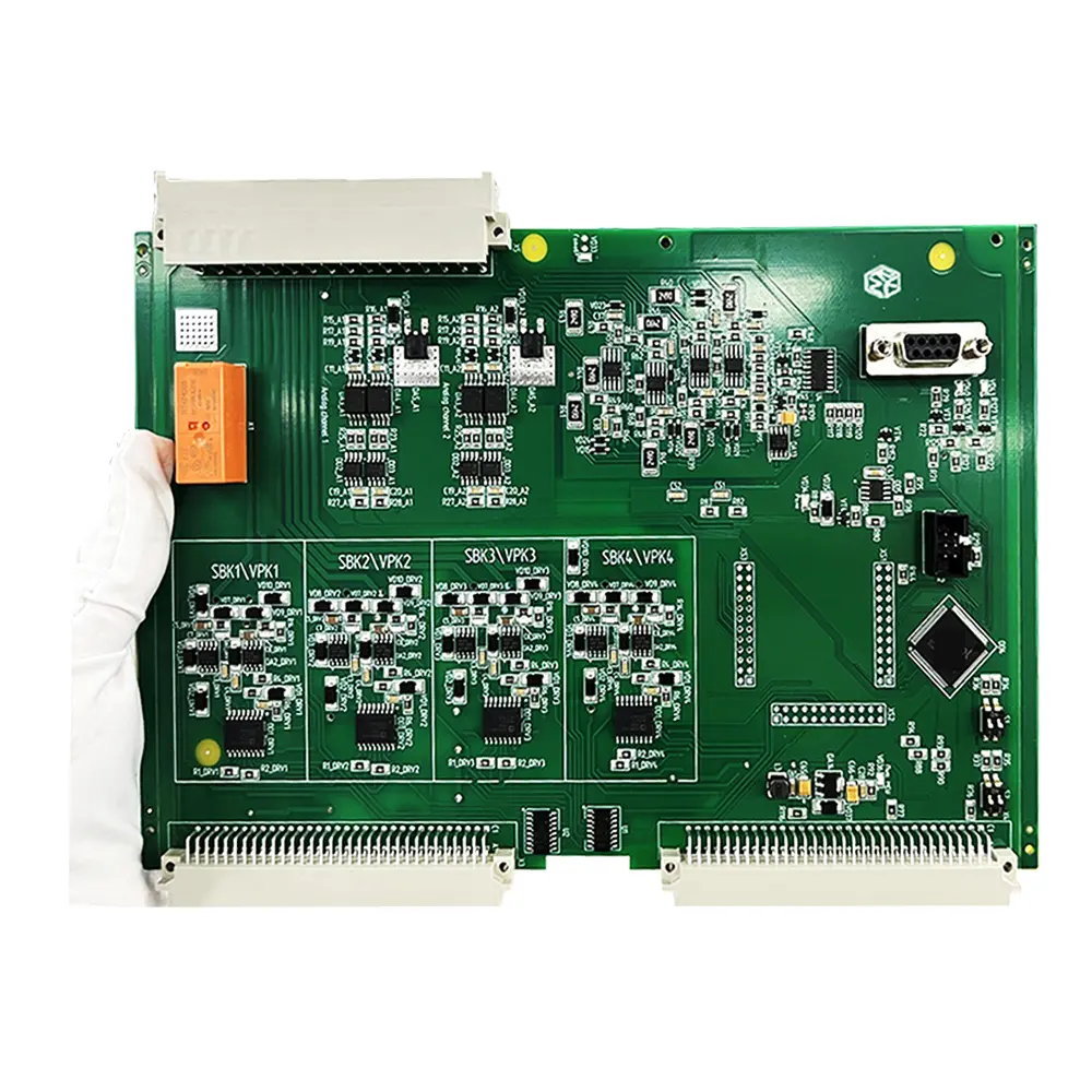
1. Main Functional Modules of Garbage Truck Controller PCBA
1.1 Control Unit
Use an automotive-grade MCU (e.g., NXP S32K series or Infineon AURIX) for logic control, CAN communication, and fault diagnosis. During PCBA layout, place the MCU close to the secondary side of the power module and away from the high-voltage drive area.
1.2 Multi-Channel Power Drive
Control hydraulic solenoid valves and DC motors. Use high-side driver ICs (e.g., TI TLV7209) or low-side MOSFET arrays. For each drive channel, provide dedicated copper pour for heat dissipation, with a copper area of no less than 100 mm².
1.3 Signal Acquisition and Isolation
Acquire signals from oil pressure sensors, limit switches, and joystick commands. Add TVS diodes and RC filters to analog inputs. Isolate digital inputs from the MCU side using optocouplers or capacitive isolators (e.g., Silicon Labs Si86xx).
1.4 CAN Bus Interface
Supports J1939 protocol for communication with the vehicle chassis. On the PCBA, the CAN transceiver (TJA1043) should have a separate ground from the MCU. Place a common-mode choke and termination resistor jumpers near the transceiver.
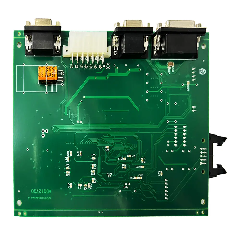
2. PCBA Design and Manufacturing Dry Goods
2.1 PCB Stack-up and Laminate
Recommended 4-layer stack-up:
- Top layer: signal and power routing
- Inner layer 1: solid ground plane (no splits)
- Inner layer 2: power plane (12V / 5V zones)
- Bottom layer: low-speed signals and auxiliary ground
Board material: FR-4 TG ≥170°C. For high-frequency drive sections, local hybrid lamination with Rogers 4003 is optional. Use 2.0mm board thickness to enhance vibration resistance.
2.2 Power and Signal Separation Rules
- Place power MOSFETs in a concentrated area, at least 15mm away from the MCU
- For high-current loops (e.g., motor drives), calculate trace width as 1mm per ampere for 1oz copper
- Place flyback diodes in parallel with all relay coils, with the diode as close as possible to the relay pins
- Control CAN differential impedance to 120Ω ±10%, with 0.8mm trace spacing
2.3 Key SMT Processes
- Use SAC305 solder paste (Sn96.5Ag3Cu0.5) for better mechanical shock resistance
- Use stepped stencils for power device pads: locally increase thickness to 0.18mm on large pads
- Perform AOI after placement to check polarity components (electrolytic capacitors, TVS, optocouplers)
- For through-hole waterproof connectors (D-sub or Deutsch), apply flux before wave soldering and preheat to 110°C
2.4 Conformal Coating and Mechanical Protection
Garbage trucks operate in humid, salt spray, and oily environments. After soldering, the PCBA shall undergo:
a. Ultrasonic cleaning (to remove ionic flux residue)
b. Spray acrylic conformal coating, 0.05mm thickness. Mask connectors, buttons, and heat sink areas with tape
c. Dispense thermal potting gel (1.5W/m·K) on critical MCU and driver chips
d. Reinforce mounting holes with copper annular rings to prevent delamination of multilayer boards
 3. Mass Production Testing and Reliability Verification
3.1 ICT In-Circuit Test
3. Mass Production Testing and Reliability Verification
3.1 ICT In-Circuit Test
Cover the following faults:
- Power-to-ground short circuits
- Wrong values or missing components on critical resistors and capacitors
- Open or short circuit on driver MOSFET gate pins
- Tolerance deviation of CAN bus termination resistors
Reserve 1.0mm diameter round test pads with a pitch ≥2.54mm.
3.2 Functional Burn-in and Temperature Cycling
Each finished PCBA shall undergo:
- Full functional test at room temperature (30 minutes)
- 24-hour continuous operation at 65°C, 85% RH
- Low-temperature start-up and CAN communication stability test at -30°C
- Sweep vibration test: 10-500Hz, 2g acceleration, 1 hour on each X/Y/Z axis
3.3 Practical EMC Improvement Experience
- Hydraulic motor start/stop in garbage trucks often causes power supply dips and excessive radiated emissions. Common corrective measures:
- Add varistor 14D471 and common-mode choke (100μH) at the power entry
- Connect ferrite beads (100Ω@100MHz) in series on solenoid valve drive outputs close to the connector
- Ground the MCU crystal oscillator housing and remove ground plane underneath to reduce capacitive coupling
- Connect an RC snubber (1MΩ + 0.1μF) between the chassis ground point and PCBA digital ground
4. Selection Reminders and Cost Control
- Use waterproof connectors from TE or Deutsch (IP67). Do not use standard pin headers or sockets.
- If relays must be used, select sealed types that are not damaged by washing solvents.
- Use 125°C low-ESR electrolytic capacitors (e.g., Rubycon YXF). Do not use 85°C general-purpose parts.
- Domestic alternative: HDSC HC32F460 can replace some STM32F4 devices, but its ADC has weaker negative voltage tolerance. Add a clamping circuit on the input.
Garbage truck controller PCBA manufacturing is challenging because it must simultaneously meet high power density, harsh electrical environments, and vibration life.
Shenzhen Kingsheng Technology Co., Ltd. has rich experience and a professional technical team in PCBA.
Contact KingshengPCBA today to request a quote or discuss your PCBA project.
 +86 13828766801
 kspcba@c-alley.com
 https://www.kingshengpcba.com/
 2/F, Building 6, Tangtou 3rd Industrial Zone, Tangtou Community, Shiyan Town, Baoan District, Shenzhen, China, 518108


