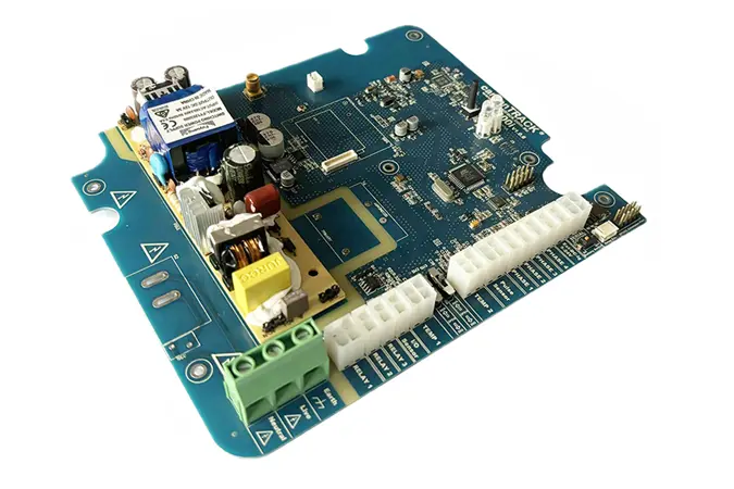
Forklift Controller PCBA: Key Technical Points from Design Selection to Soldering Process
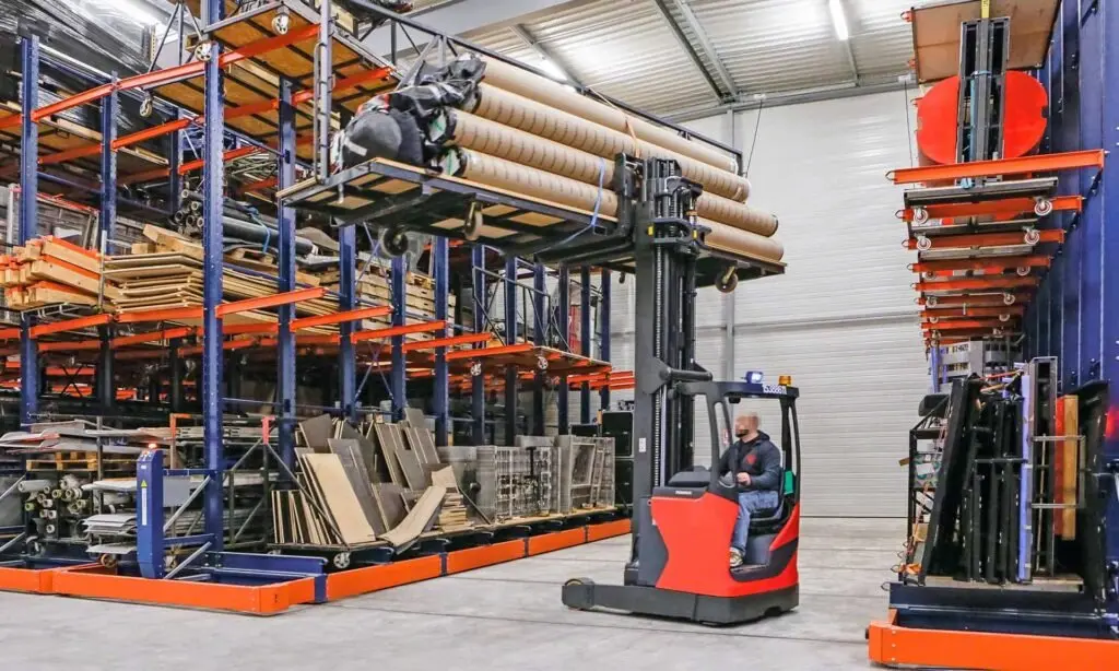
As the core electronic component of industrial vehicles, the forklift controller is responsible for signal acquisition, drive control, and communication interaction. The quality of its
PCBA directly affects the forklift's operational precision, response speed, and service life. With the popularity of electric forklifts and AGVs (Automated Guided Vehicles), higher requirements have been placed on the controller's vibration resistance, wide operating temperature range (-40°C to 85°C), and electromagnetic interference immunity. This article outlines the key technical nodes of
forklift controller PCBA from a practical manufacturing perspective, providing reference for independent website customers in selection and quality control.
 I. Key Factors in the Design Phase
1.1 Substrate Material Selection
I. Key Factors in the Design Phase
1.1 Substrate Material Selection
Forklift controllers often operate in high-humidity, high-vibration environments. FR-4 glass fiber board is a general choice, but a high-Tg material (glass transition temperature ≥150°C) is required to prevent substrate softening due to long-term heat exposure. For high-current drive applications (e.g., hydraulic pump motor control), localized aluminum-based boards should be used for heat dissipation.
1.2 Circuit Layout Principles
- Power zone and signal zone isolation: Maintain a minimum gap of 5mm between power components (MOSFETs, relays) and MCU, CAN communication chips, or separate them with a ground trace trench.
- Reinforced mounting for connectors: Provide positioning holes around all external wiring interfaces (e.g., encoder, accelerator pedal input) for subsequent adhesive dispensing or mounting bracket installation.
II. Component Selection Pitfalls to Avoid
2.1 Connector Selection
Sealed connectors from TE or Molex with a protection rating of at least IP54 are recommended. Common issue: self-procured domestic connectors may suffer from plastic embrittlement below -20°C, leading to poor contact.
2.2 Capacitors and Resistors
- MLCC capacitors: Avoid large-value (≥10μF) X7R capacitors, as their piezoelectric effect generates noise under forklift vibration. Replace with tantalum or film capacitors.
- Current sensing resistors: Must use alloy chip resistors (temperature drift ≤50ppm/°C) in current detection loops. Ordinary thick-film resistors exhibit resistance drift exceeding 5% under temperature changes, causing false overcurrent detection.
III. Assembly and Soldering Process Control
3.1 Solder Paste and Stencil
Use SAC305 (Sn96.5Ag3Cu0.5) lead-free solder paste. For high-power component pads on forklift controllers (e.g., TO-247 packaged MOSFETs), the stencil should be locally thickened to 0.15mm-0.18mm to prevent insufficient solder, which leads to increased contact resistance and heat generation.
3.2 Reflow Soldering Temperature Profile
For boards containing QFP or BGA packaged chips, the peak temperature should be maintained at 245±3°C, with the time above liquidus (217°C) kept between 60-90 seconds. Common defect: insufficient peak temperature leads to cold solder joints, causing signal interruption under forklift vibration.
3.3 Wave Soldering Fixture Protection
For through-hole components such as pin-type relays and connectors, a fixture should be used to shield pre-assembded sensitive chips before wave soldering to prevent solder splashes causing short circuits.
 IV. Post-Process Reinforcement Techniques
4.1 Conformal Coating Application
IV. Post-Process Reinforcement Techniques
4.1 Conformal Coating Application
Forklift controller PCBA must be fully coated with acrylic or polyurethane conformal coating to a thickness of 0.05-0.1mm. Key areas: MCU pin bottoms, areas around crystals, and unsealed potentiometers. UV inspection is required to verify coverage integrity.
4.2 Component Underfill and Staking
Components taller than 8mm (electrolytic capacitors, inductors) and connectors near board edges must be underfilled or corner-staked using two-part epoxy adhesive. Curing condition: 30 minutes at 80°C, achieving 5G random vibration test capability.
V. Factory Testing and Aging
5.1 In-Circuit Test (ICT)
Cover the following nodes: power-to-ground shorts, critical voltage points (5V, 3.3V, 15V), and CAN bus termination resistance (60Ω±5%). Recommended test probe contact pressure: 150g-200g to avoid damaging solder joints.
5.2 Thermal Cycling Aging
Test profile: Hold at -40°C for 30 minutes, then ramp to 85°C within 10 minutes and hold for 30 minutes. Repeat for 10 cycles. During the test, continuously power the controller and simulate throttle signals, monitoring whether PWM duty cycle drift exceeds 2%.
5.3 Vibration Testing
Per ISO 16750-3 standard, random vibration power spectral density: 0.05g²/Hz (10-100Hz), 8 hours per axis. Post-test inspect screw torque (recommended M3 torque: 0.5N·m) and solder joint cracks.
Conclusion
The difficulty of forklift controller PCBA manufacturing lies not in high-density routing, but in three fundamental reliability factors: vibration resistance, temperature tolerance, and moisture protection. When assisting customers with selection, independent website operators are advised to request vibration test reports and conformal coating thickness inspection records. For applications in cold storage or port machinery, additional salt spray testing (5% NaCl, 48 hours) is required.
Shenzhen Kingsheng Technology Co., Ltd. has rich experience and a professional technical team in PCBA.
Contact KingshengPCBA today to request a quote or discuss your PCBA project.

 +86 13828766801
 kspcba@c-alley.com
 https://www.kingshengpcba.com/
 2/F, Building 6, Tangtou 3rd Industrial Zone, Tangtou Community, Shiyan Town, Baoan District, Shenzhen, China, 518108


