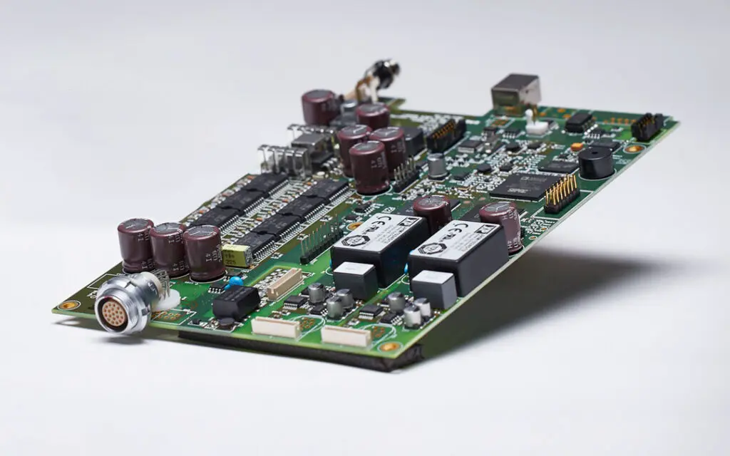
Image-Guided Puncture Surgical Positioning System PCBA: Three Technical Difficulties in Precision Manufacturing and Their Breakthroughs
I. Product Background and PCBA Functional Positioning
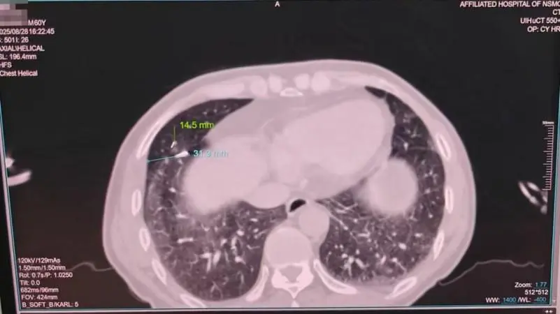
The image-guided puncture surgical positioning system is used in minimally invasive procedures such as tumor biopsy and ablation therapy. As the core control unit of the system, the PCBA performs the following functions: real-time processing of CT or MRI image data, controlling the robotic arm trajectory, managing sensor feedback, and ensuring electromagnetic compatibility to avoid interference with intraoperative imaging.
 II. Manufacturing Difficulty 1: Crosstalk Suppression Between High-Speed Image Signals and Motion Control
1. Problem Description
II. Manufacturing Difficulty 1: Crosstalk Suppression Between High-Speed Image Signals and Motion Control
1. Problem Description
The PCBA contains a DDR4 image cache bus (operating frequency above 1600MHz), stepper motor drive circuits (PWM switching frequency 20-50kHz), and high-precision encoder interfaces (differential signals). Harmonic components of the high-speed digital signals fall into the sensitive frequency range of the motor drive, causing noise in position feedback. This results in a positioning error exceeding ±0.3mm.
2. Process Countermeasures
- Six-layer board stack-up structure: Top layer (signals), second layer (continuous ground plane), third layer (power), fourth layer (low-speed signals), fifth layer (auxiliary ground), bottom layer (sensitive signals). The image bus is routed on the top layer, with the ground plane on the second layer providing a return path and isolating noise.
- The motor driver is placed separately at the edge of the PCBA, maintaining a physical isolation distance of more than 30mm from the image processor. The power ground of the driver is connected to the main ground plane at a single point via a 0-ohm resistor.
- A ground trace is inserted between differential encoder signal pairs, with a trace spacing equal to three times the trace width, to control differential-mode radiation.
III. Manufacturing Difficulty 2: Soldering and Rework Control of High-Density BGA Components
1. Problem Description
The system uses a 0.8mm pitch, 256-pin BGA image processor and 0.5mm pitch DDR4 memory modules. In production, head-in-pillow defects and solder voids have been observed, with void rates exceeding 15%. During rework, bridging between adjacent solder balls presents a high risk.
2. Process Countermeasures
- Stencil design: BGA pad openings are reduced to 90% of the actual pad size, using circular chamfered apertures and an electroformed stencil thickness of 0.12mm. A segmented reflow profile is used: the soaking zone is extended to 90 seconds, with a peak temperature of 243±2℃.
- Vacuum reflow soldering with nitrogen protection, maintaining oxygen levels below 1000ppm. X-ray inspection is performed on 3 randomly selected boards per batch, with void rates controlled below 8%.
- Rework process: A non-contact infrared bottom preheater set to 150℃ is used. After removing the chip, residual solder is cleared using copper braid and flux. The area is cleaned, low-temperature solder paste is applied via printing, and the component is reattached.
IV. Manufacturing Difficulty 3: Medical-Grade EMC and Electrical Safety Compliance
1. Problem Description
The product must pass the IEC 60601-1-2 (4th edition) electromagnetic compatibility tests. During initial submission, radiated emissions exceeded the limit by 8dB in the 150MHz-200MHz frequency range. Electrostatic discharge of ±8kV (air discharge) caused the image processing unit to reset.
2. Process Countermeasures
- All external interfaces on the PCBA (USB, HDMI, encoder interfaces) are fitted with common-mode chokes and TVS diode arrays. Common-mode chokes are selected with an impedance of 600Ω@100MHz. Interface grounds are connected to the chassis ground via 1nF high-voltage capacitors.
- ESD protection path: A 10pF capacitor is connected in parallel to the reset signal line, with a 100Ω resistor in series. Ground vias are placed on both sides of sensitive signal lines, with a via spacing less than 1/20 of the signal wavelength.
- During final assembly, conductive foam is used between the PCBA mounting screws and the chassis to ensure low-impedance grounding. A shielding cover is added and soldered to the PCBA's ground pads at four points.
 V. Summary
The manufacturing difficulties of the image-guided puncture surgical positioning system PCBA center on signal integrity, soldering reliability, and medical electromagnetic compatibility. The process solutions described above have been verified in mass production: positioning control accuracy reaches ±0.15mm, first-pass BGA yield is 98.3%, and the product meets the YY 0505-2012 standard.
Shenzhen Kingsheng Technology Co., Ltd. has rich experience and a professional technical team in PCBA.
Contact KingshengPCBA today to request a quote or discuss your PCBA project.
 +86 13828766801
 kspcba@c-alley.com
 https://www.kingshengpcba.com/
 2/F, Building 6, Tangtou 3rd Industrial Zone, Tangtou Community, Shiyan Town, Baoan District, Shenzhen, China, 518108


